
AI Assistant
Cart
Quote
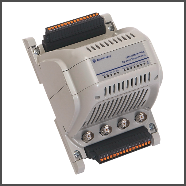
Dynamic Measurement Module
SKU: 1444-DYN04-01RA
Out of stock
Availability: Out of Stock
Marketplace sellers
Submit a quote request to receive offers from sellers of this product.
Short Description
Dynamic Measurement Module.
Buy currently uses Select Automation shop pricing and checkout.
Specifications:
Buffer Outputs: 4.
Control Output: 1 SPDT, +opt RELX (4 SPDT) x3.
Interface: Ethernet/IP.
Number Of Channels: 4.
Number of status indicators: 16.
Speed Inputs: 2.
Status indicator: Power, Module status, Network status, Processor status, Processor operating state, DSP status, DSP operating state, Channel status (4), Relay status, Ethernet link status (2), Ethernet activity indicator (2).
Transducer Power: IEPE Accel, ECP's, Volts.
Conductor type: Copper.
Connections: Terminal pin.
Consumption: 11.5 W.
Current: 411mA @ 24V (546...319mA @ 18...32V).
Dissipation: 9 W.
Ethernet: True.
Isolation voltage: 50V (continuous), basic insulation type between Ethernet, power, ground, and AUX bus, 50V (continuous), basic insulation type between signal ports, power, ground, and AUX bus, 250V (continuous), basic insulation type between relay ports and system, No.
Model: Basic device.
Number of connections: 2.
Number of indicator outputs: 16.
Number of sensor inputs for IEPE sensors: 4.
Power monitor: The two power supply voltage levels are monitored. status indicated via process operating status indicators and on controller input (I/O).
Redundant power: Two 18...32V DC, max 8 A SELV power supply inputs, Higher voltage supply is applied to main and expansion modules.
Suitable for bus connection: True.
Supply voltage: 32V DC.
Supply voltage DC: 18 V.
Type of electric connection: Spring clA connection.
Voltage type of supply voltage: DC.
Wire type: Shielded on signal connections, Only Shielded on Ethernet ports, Unshielded on power and relay ports.
Contact arrangement: Single pole double throw (SPDT) change-over contact.
Contact material: Gold plated surface material.
Electrical life cycles, min: 50000.
Faults: Main module fault, Main module tachom fault, Expansion module fault, Ethernet network fault, Expansion bus fault.
Inductive load: 5A @ 250V AC.
Mechanical life operations, min: 10000000.
Number of relays: 1.
Operating time, max: 15 MS @ rated voltage.
Permissible load, min: 10mA @ 5V DC.
Rated carry current: 8 A.
Rated current, max: 8 A AC.
Rated voltage, max: 250V AC.
Releasing time, max: 5 MS rated voltage.
Resistive load: 8A @ 250V AC.
Switching capacity, max: 90 W DC inductive load.
Voted alarm: Assign to any enabled voted alarm (0...12).
Conversion: 24 bits.
Dynamic range: 80 dBfs (0.01% fs), 90 dBfs.
Sample rate: 93 KS/s, 2 channels.
Controller & System I/O:
Alarm reset: Alarm gate control.
Alarm status: Channel setup.
Aux processor: DSP processor.
Data speed: Alarm limits (16).
Relay status: Expansion module.
Set point multiplier enable: Alarm buffer reset.
Trend alarm: Transducer.
Trips inhibit: Alarm buffer trigger.
Input Signals:
Detection threshold: Fixed (-2.5V DC).
Impedance: >100 kΩ.
Isolation: Non-isolated, single-ended analog inputs. sensor signal returns must be isolated from ground.
Local bus inputs: Opto-isolated TTL input for signal and TX status.
Number of channel inputs: 4.
Number of digital inputs: 2.
Number of tachometer inputs: 2.
Protection: Reverse polarity.
Sensor types: CP accelerom (CCS), Dynamic pressure transducers, Dual sensors (acceleration + temperature), Eddy current probe systems (-24V DC), Self-powered sensors, Voltage signals.
Terminal inputs: TTL class with internal pull-up resistor (5V DC).
Transducer fault detection: Bias level high / low limits, Current threshold level monitoring, which is implemented in hardware for -24V supplied sensors. provides the fastest fault detection possible with excellent reliability.
Transducer negative power: Voltage regulated: -24V/25 Ma.
Transducer positive power: Voltage regulated: 24V/25 mA.
Transducer status: Only local bus inputs.
Voltage ranges: ±24V DC.
Output Signals:
Application: Trip inhibit/bypass, Alarm/relay reset, Alarm SPM/gate control 0, 1, Tachom 0, 1 status.
BNC: Surge protection: No.
Notes: All outputs are single ended and have no isolation, Buffered output is not representative of input when no load (sensor) is connected to the associated measurement channel, Confirm that the connected instrumentation does not provide power, such as if to.
Number of buffered outputs: 4.
Number of digital outputs: 2.
Terminal pins: Surge protection: No.
Communication: A digital network that is used between a main module and its expansion modules is implemented on the local bus. Communication does not link main modules.
Communication protocol: ODVA-compliant (conformance tested) EtherNet/IP industrial protocol.
Concurrent access: Controller (owner), Up to 3 (more) sessions.
IP address: Set by hardware switch on the terminal base as 192.168.0.xxx (last octet set by switch), Set in configuration using DHCP/BOOTP tools.
Power: Passes power from each main module (1444-DYN04-01RA) to its expansion modules, Power is not passed between main modules, when redundant power supplies are connected to a main module, only the voted power source is distributed to its expansion modules.
Supported connectivity protocols: Single Ethernet (IEEE 802.3), Device Level Ring (ODVA).
TTL signals: Dual independent TTL signals, with tachom sensor status, are passed on the Local Bus, there can be only one tachom expansion module on a local bus, The TTL signal can serve up to six main modules.
Measurement Modes & Configuration:
ADC out: Signal out of the ADC.
Alternate path: Alternate signal path.
Four channel dynamic (4 kHz): Dual path: Measurement is the same as “four channel dynamic (4 kHz) or static, Inputs are internally connected between channels 0 and 2 and between channels 1 and 3.
Four channel dynamic (4 kHz) or static: All channels are available. Each channel pair can be defined for either Static (DC) or Dynamic (AC) measurements, Dynamic channels can be configured for an FMAX up to 4578 Hz (274.7 kCPM).
Mid filter: Before high pass filter and integration.
Multiplexed: Configuration dependent.
Post filter: After high pass filter and integration.
Two channel dynamic (20 kHz): 2 channel static: channels 0 and 1 can be configured for Dynamic (AC) measurements with an FMAX of up to 20.6 kHz (1236 kCPM), Channels 2 and 3 are available for Static (DC) measurements.
Two channel dynamic (40 kHz): Channels 0 and 1 (pair) can be configured for Dynamic (AC) measurements with a measurement span of 40 kHz (1), or as gSE. Channels 2 and 3 are disabled (off).
Measurement Types & Capabilities:
Bias/gap: Number per channel: 1.
DC measurement types: Proportional voltage.
Data format: 32-bit float.
Data source: Selectable: post filter, mid filter, alternate path.
FFT: Windows: none, flat top, hamming, Hanning.
FFT bands: Order domain speed ref: 0, 1.
Measurement type: Rod drop.
Not 1x: Number per channel: 1.
Overall: Time constant.
Real time: 500 Ms.
SMAX: Per channel pair.
Shaft absolute: Per channel pair.
Time waveform: SAle rate: ≤Fmax.
Tracking filters: Roll Off: -48 dB/octave.
Trigger source: Speed reference: 0 or 1.
Type: TTL class.
gSE FFT: Number per channel: 1.
gSE overall: Number per channel: 1.
Speed Measurement:
Mode: Redundant: Speed 0 = Speed 1 when tach 0 in fault.
Speed: Terminal pin: TTL.
Speed acceleration: Update rate: 1 / s.
Speed, max: 1 per speed measurement, Maximum speed since reset, Reset via controller I/O.
Timing & Synchronization:
Accuracy: Maximum drift: 100 MS per year.
Synchronization: Clock synchronized to controller time per IEEE-1588 V2 / CIP sync (ODVA) standard.
Alarms:
Alarm form: Over/under threshold.
Alarm logic: 1oo1, 1oo2, 2oo2, 1oo3, 2oo3, 3oo3, 1oo4, 2oo4, 3oo4, 4oo4, 1oo2 AND 1oo2. 2oo2 OR 2oo2,1oo2 AND 2oo2, 2oo2 AND 1oo2.
Deadband: 0 %.
Delay times: Separate delay times for alert and danger alarms.
Failsafe: If assigned to a relay, when in alarm the relay coil is deenergized.
High-resolution samples: SAled rate: 100 Ms.
I/O gating control: Alarm is evaluated when gate condition is true, Control on either of two controller output (I/O) bit, Control on either of two digital inputs (hardware).
I/O Logix control: Alarm actuates when logic control is set, Control on either of two controller output (I/O) bit, Control on either of two digital inputs (hardware).
Input condition: Alert, Danger, Transducer fault.
Input parameter: Any real-time or discrete continuous measurement.
Latching: Non-latching, resets when condition clears, Latching, after condition clears, resets upon command via controller I/O.
Logic inputs: 1...4 measurement alarms.
Number: Voted alarms: 13.
Processing mode: Profile: limits that are read from controller I/O
SPM control source: Controller I/O SPM control bit 0 or 1/digital input 0 or 1
SPM timer: Number of s the SPM is applied after SPM signal is reset, From 0...65.5 s in 0.1 s increments
Saved trend buffer: 640 static records: includes N% records sAled post trigger
Set point multiplier range: 0.1...100x: Multiply the threshold limits by this value when invoked. Can be static: enabled by controller I/O or manual switch
Speed gating control: Speed reference: 0, 1, Condition (>, <, <>, ><), Speed limits (low, high)
Sustain time: 1.0 s (fixed)
Transducer state consideration: OK required, Not OK forces alarm, OK status is not considered.
Fault Management:
Controller I/O: Status bit on controller input table.
Expansion bus time-out: 100 MS (fixed).
Indication: Update status indicator.
Relay action: Select faults on any of Module, select fault on any of Expansion modules, select fault on any of Ethernet, Select fault on any of Expansion bus.
Data:
Buffers: Four buffers each containing: 640 discrete records, 64 dynamic records.
Definition: Speed Source: 0.1, Transient minimum, Transient maximum speed, Startup: speed increases from under to over the maximum speed, Coast down: speed decreases from over to under the maximum speed.
Dynamic data: SAle rate (1): N x 100 Ms.
Enable: Enable static data capture, Enable dynamic data capture.
Overflow: When enabled allows buffers of up to 2560 discrete and 256 dynamic records.
Record content: Dynamic data: TWF and FFT per channel.
Sample Intervals: At delta RPM (off or 1...1000 RPM), At delta time (off or ≥ 1 s), Post start-up time, Dynamic records are captured every tenth trigger.
Static data: SAle rate: N x 100 Ms.
Logging:
Conditions: 35 logged conditions, Categorized by event type.
Event types: System, Alarm, Buffer.
Number of entries: 1500 total records, 256 records per event type.
Time stamp resolution: 0.1 Ms
Absolute shaft: Per channel pair, Ch-0/2: displacement, Ch-1/3: acceleration or velocity, Relative mounting: 0°, 180°.
Asynchronous mode FMAX: 30 Hz.
Bandwidth FMAX: 0.035 khz.
Frequency max: Surveillance: 40 kHz (OA only).
High pass filter: -3 dB corner: 0.1 Hz to 1 kHz, -24, -60 dB/octave.
Integration: None, single or double.
Low pass filter: -3 dB corner 10 Hz to 40 kHz, -24, -60 dB/octave.
Resolution: 3 µV (theoretical).
Sampling mode: Synchronous.
Signal detection: Peak to peak, Peak, RMS, Calculated peak to peak, Calculated peak.
Synchronous mode: Tachom source: 0, 1, SAles per rev: 8...128, Orders: 2.0...31.3.
gSE: 2 gSE channels max, only 2-channel protection or surveillance modes, Overall, only TWF/FFT, HPF: 200, 500 Hz, 1, 2, 5 kHz, FFT FMAX: 100 Hz...5 kHz.
Conducted RF immunity: 10V rms with 1 kHz sinewave 80% AM from 150 kHz...80 MHz
Conductor/insulation temperature rating, min: 85 °C.
Conformal coating: All printed circuit boards are conformal coated in accordance with IPC-A-610C and in compliance with: IPC-CC-830 B, UL508.
EFT/B immunity: ±2kV 5kHz on unshielded power ports, ±2kV 5kHz on shielded signal ports, ±2kV 5kHz on shielded Ethernet ports, ±3kV 5kHz on unshielded relay ports.
ESD immunity: 6 kV contact discharges, 8 kV air discharges.
Emissions: IEC 61000-6-4.
Nonoperating temperature: -40 °C.
Operating temperature: -25 °C.
Operating temperature (screw type only), max: 115 °C.
Operating temperature (spring type only), max: 105 °C.
Radiated RF immunity: 10 V/m with 1 kHz sinewave 80% AM from 80...2000 MHz, 10 V/m with 200 Hz 50% Pulse 100% AM 900 MHz, 1 V/m with 1 kHz sinewave 80% AM from 2000...2700 MHz
Relative humidity: 5...95% noncondensing.
Shock: Operating: 15 G.
Surge transient immunity: ±1 kV line-line (DM) and ±2 kV line-earth (CM) on unshielded power and relay ports, ±2 kV line-earth (CM) on shielded signal ports, ±2 kV line-earth (CM) on shielded Ethernet ports.
Surrounding air temperature, max: 70 °C.
Vibration: 2.0 G @ 10…500 Hz.
Depth: Without terminal base: 154 mm (6.06 in).
Enclosure type rating: None (open style).
Height: Without terminal base: 106 mm (4.17 in).
Modular expandable: True.
Number of rotational speed inputs: 2.
Type of fastening: DIN rail (top hat rail).
Width: Without terminal base: 102 mm (4.02 in).
Conductor UL/cUL AWG (screw type only): 0.05 mm².
Conductor UL/cUL AWG (spring type only): 0.08 mm².
Conductor UL/cUL AWG (spring type only), max: 1.5 mm².
Conductor cross section AWG/kcmil: 0.08.
Conductor cross section solid or stranded: 0.14.
Conductor cross-section stranded with ferrule with plastic sleeve: 0.25.
Conductor cross-section stranded with ferrule without plastic sleeve: 0.25.
Stripping length: 9 mm.
Torque (screw type only): 0.22 nm.
Weight: Without terminal base: 0.40 kg (0.88 lb).
Wiring category: 2 - on signal ports, 2 - on power ports, 2 - on communications ports, 1 - on relay ports.
Integrated Condition Monitoring System Dynamix ™ 1444
Machinery protection and condition monitoring of rotating and reciprocating assets.
Distributed I/O on Ethernet/IP.
Easy integration and setup in Studio 5000 Logix Designer®.
Rugged, conformally coated and approved for electrical safety and hazardous areas.
Expansion modules available for additional capabilities.
Enable Smart Machine strategy with the Dynamix 1444 series.
Don’t let unplanned downtime impact your manufacturing objectives.
The Dynamix 1444 series provide a distributed solution for protecting or monitoring the condition of your critical machinery.
The dynamic measurement module can support dynamic and static measurements to realize the benefits of a condition-based maintenance or a predictive maintenance program.
As a part of Rockwell Automation’s Integrated Architecture, other system components such as controllers, visualization products, other input/output products, and more can be easily applied to meet the specific needs of the application.